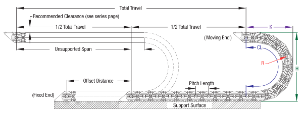
Carrier Length = (Total Machine Travel/2) + Curve Length + Offset
For minimum carrier length, moving bracket should be mounted directly above fixed bracket when machine is in center of travel. Offset is the dimension between fixed and moving bracket at center of travel.
Curve Height (H)
The overall height of the carrier at the loop. While (H) is the designed height at the loop, clearance should be provided above the carrier. This will be true of either metal or plastic carrier to account for built-in camber. Gortrac® carriers have a positive camber or pre-tension designed into the links in order to provide additional self-supporting length in horizontally oriented applications. This camber adds to the clearance required above the track. (See “Recommended Clearance” specification included in the carrier side view diagram for each product Series). In applications with limited space or non-horizontal orientations, this camber can be reduced or eliminated. For details, including any resulting reductions in unsupported span, please let Dynatect know.
Carrier Bend Radius (R)
Minimum bend radius of the cable and hose carrier should be larger than the recommended bend radius of the stiffest cable or hose installed in the carrier. Consult with cable or hose manufacturer for recommended bend radius.
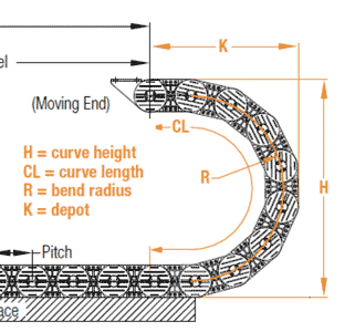
Curve Length (CL) = (π x Radius ‘R’) + (Pitch x 2)
Curve length is dependent on radius and link pitch – refer to Series specifications.
Pitch
Refers to the distance between the pivot point centerlines of adjacent links.
Depot (K)
The centerline from the first link pivot point to the end of the carrier in retraction.
Load
The total weight of the cables and hoses within the carrier. This is usually called out in pounds per foot. If hoses will contain liquid, please include that weight.
Maximum Speed
The maximum velocity of the moving end of the carrier during its travel.
Maximum Acceleration
The maximum acceleration of the moving end of the carrier during its travel.
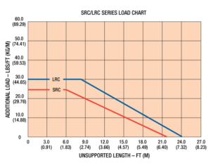
Unsupported Span
Every carrier has an unsupported span. This span is a condition of link construction and the fill weight of the cables and hoses being carried. As the unsupported span of the carrier is exceeded, the carrier begins to sag. Gortrac will recommend proper support guidance when carrier fill weight exceeds its free carrying length. Refer to Product Series specifications for load charts.
Metal vs. Plastic Carriers
Gortrac offers plastic, metal and hybrid carriers to satisfy the broadest range of applications. Read more about plastic vs. metal cable/hose carriers >
Open-Style vs. Enclosed- Style Carriers
Gortrac offers both open and enclosed style options. Open-style carriers provide easy cable/hose inspection, while enclosed-style carriers offer protection from damaging outside elements such as hot chips.
