Design Specs - English
How To Create A Part Number:
Model – Height – Separators – Length – Bracket (fixed) – Bracket (moving)
Example: KL3-18-1-60.49-STD#3-STD#3
⇒ Length is specified in inches, to two decimals. It is the distance between flanges
⇒ (see formula on carrier side view diagram)
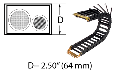
⇒ The standard separator placement is every 4th link. Please specify the number of separators specified per cavity.
⇒ Vertical cavity separators snap into carrier cross bars to provide multiple compartments in a single link.
Carrier Cross Sectional View

| Model |
A (inside width) |
C (outside width) |
Weight (lb/ft) |
| KL200* |
2.00 |
2.75 |
1 |
| KL1** |
3.00 |
3.75 |
0.98 |
| KL2 |
4.50 |
5.25 |
1.11 |
| KL3 |
7.00 |
7.75 |
1.48 |
*New model: KL200-10 or KL200-15 – hinged bars available on inside (standard) or outside radius. When specifying, please note preferred location of hinged bars.
**KL1 – optional single-piece cavity divider available.
Specifications are listed as inches unless otherwise noted
Carrier Side View
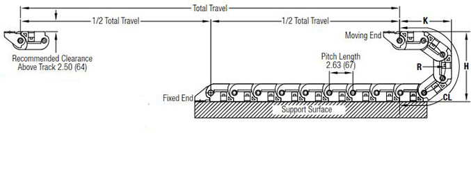
Travel/2 + CL (+ Offset Distance From Center*) = Length
Dynatect recommends mounting the stationary end of the carrier at the center of travel, minimizing the required length.
In cases where center mounting is not possible, add the distance offset from center to the carrier length calculation.
| Height |
R (bend radius) |
H (curve height) |
K (depot) |
CL (curve length) |
| 10* |
3.75 |
10.00 |
7.59 |
16.80 |
| 15* |
6.25 |
15.00 |
10.08 |
24.70 |
| 85 |
3.00 |
8.50 |
6.88 |
14.68 |
| 12 |
4.75 |
12.00 |
8.63 |
20.18 |
| 14 |
5.75 |
14.00 |
9.63 |
23.31 |
| 18 |
7.75 |
18.00 |
11.60 |
29.50 |
| 26 |
11.75 |
26.00 |
15.60 |
42.18 |
*10 and 15 Height No. with KL200 model only (KL200-10 or KL200-15).
Specifications are listed as inches unless otherwise noted
Design Specs - Metric
How To Create A Part Number:
Model – Height – Separators – Length – Bracket (fixed) – Bracket (moving)
Example: KL3-18-1-60.49-STD#3-STD#3
⇒ The standard separator placement is every 4th link. Please specify the number of separators specified per cavity.
⇒ Vertical cavity separators snap into carrier cross bars to provide multiple compartments in a single link.
⇒ Length is specified in inches, to two decimals. It is the distance between flanges
⇒ (see formula on carrier side view diagram)
Carrier Cross Sectional View

| Model |
A (inside width) |
C (outside width) |
Weight (kg/m) |
| KL200* |
51 |
70 |
1.49 |
| KL1** |
76 |
95 |
1.46 |
| KL2 |
114 |
133 |
1.65 |
| KL3 |
178 |
197 |
2.2 |
*New model: KL200-10 or KL200-15 – hinged bars available on inside (standard) or outside radius. When specifying, please note preferred location of hinged bars.
Specifications are listed as millimeters unless otherwise noted
Carrier Side View

Travel/2 + CL (+ Offset Distance From Center*) = Length
Dynatect recommends mounting the stationary end of the carrier at the center of travel, minimizing the required length.
In cases where center mounting is not possible, add the distance offset from center to the carrier length calculation.
| Height |
R (bend radius) |
H (curve height) |
K (depot) |
CL (curve length) |
| 10* |
95 |
254 |
193 |
427 |
| 15* |
159 |
381 |
256 |
627 |
| 85 |
76 |
216 |
175 |
373 |
| 12 |
121 |
305 |
219 |
513 |
| 14 |
146 |
356 |
244 |
592 |
| 18 |
197 |
457 |
295 |
749 |
| 26 |
298 |
660 |
396 |
1071 |
*10 and 15 Height No. with KL200 model only (KL200-10 or KL200-15).
Specifications are listed as millimeters unless otherwise noted
Mounting Brackets
Bracket Arrangements

Mounting Bracket Diagram & Dimensions
Strain Relief Brackets are optional. Universal mounting brackets are available (drawings below).
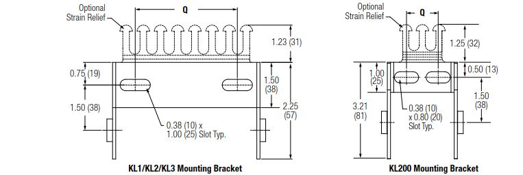
| Model No. |
Q in(mm) |
| KL200* |
1.05 (27) |
| KL1** |
1.88 (48) |
| KL2 |
3.38 (86) |
| KL3 |
5.88 (149) |
Universal brackets are available:
