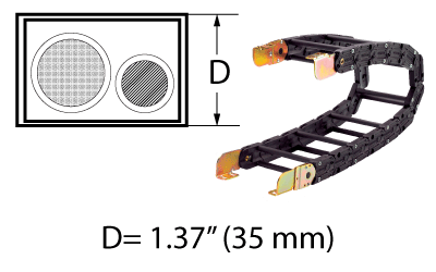
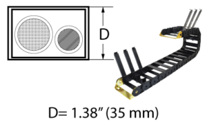
The NSB Series are modular link plastic carriers with an overall 1.37 inch (35mm) overall link height and 2 standard minimum bend radii. The tongue-and-groove design and the aluminum cross bars result in a nearly indestructible cable carrier.
How To Create A Part Number: Model – Bar Style – Bar Width – Height – Separators – Length – Bracket (fixed) – Bracket (moving)
Example: NSB-PR-4.50-55-1-72.89-#1IN-#1IN
⇒ Length is specified in inches, to two decimals. It is the distance between flanges ⇒ (see formula on carrier side view diagram)
⇒ Specify bracket type and arrangement # for each end
Cross Bar Styles:
– PR = Poly Roller (over bolted aluminum round bar)
– RB = Aluminum Round Bar
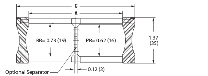
Carrier Cross Sectional View
Model
Bar Style
A
(inner width)
C (outer width)
Weight (lb/ft)
NSB
PR/RB
Customer Specified
A + 0.94
0.70
Specifications are listed as inches unless otherwise noted
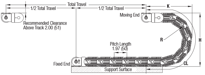
Carrier Side View
Travel/2 + CL (+ Offset Distance From Center*) = Length
Dynatect recommends mounting the stationary end of the carrier at the center of travel, minimizing the required length.
In cases where center mounting is not possible, add the distance offset from center to the carrier length calculation.
Height
R (bend radius)
H (curve height)
K (depot)
CL (curve length)
55
2.39
6.17
5.13
11.50
75
3.06
7.50
5.88
13.75
Specifications are listed as inches unless otherwise noted
Design Specs - Metric
How To Create A Part Number: Model – Bar Style – Bar Width – Height – Separators – Length – Bracket (fixed) – Bracket (moving)
Example: NSB-PR-4.50-55-1-72.89-#1IN-#1IN
⇒ Length is specified in inches, to two decimals. It is the distance between flanges ⇒ (see formula on carrier side view diagram)
⇒ Specify bracket type and arrangement # for each end
Cross Bar Styles:
– PR = Poly Roller (over bolted aluminum round bar)
– RB = Aluminum Round Bar
Carrier Cross Sectional View
Model
Bar Style
A
(inner width)
C (outer width)
Weight (kg/m)
NSB
PR/RB
Customer Specified
A + 24
1.04
Specifications are listed as millimeters unless otherwise noted
Carrier Side View
Travel/2 + CL (+ Offset Distance From Center*) = Length
Dynatect recommends mounting the stationary end of the carrier at the center of travel, minimizing the required length.
In cases where center mounting is not possible, add the distance offset from center to the carrier length calculation.
Height
R (bend radius)
H (curve height)
K (depot)
CL (curve length)
55
61
157
130
292
75
78
191
149
349
Specifications are listed as millimeters unless otherwise noted
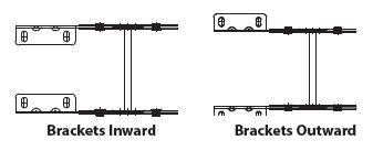
Mounting Brackets
Specify bracket arrangement and direction of flange. Mounting holes can be inward facing or outward facing.
Example: #1 arrangement and inward facing holes = #1-IN
Example: #4 arrangement and outward facing holes = #4-OUT
Standard Mounting Bracket Arrangements
Bracket Flange Mounting Hole Location
Bracket Mounting Hole Dimensions (Top View)
Specifications are listed as: inches (millimeters) unless otherwise noted