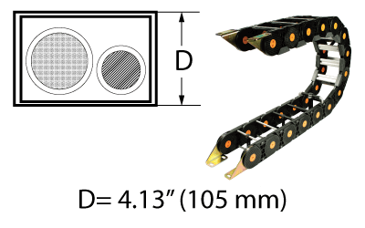
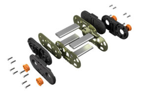
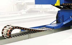
The TL series is a large size modular link plastic carrier. The TL series is excellent for robotics, long travel and heavy-duty industrial applications. Standard and universal mounting bracket options are available.
Inside Width: Several snap-in plastic crossbars are available in fixed cavity widths from 3.93″ to 13.63″. All other crossbar options are customer-specified.
Model – Bar Style – Bar Width – Height – Separators – Length – Bracket (fixed) – Bracket (moving)
Example: TL-MB-5.73-160-0-72.23-#1IN-#1IN
⇒ Length is specified in inches, to two decimals. It is the distance between flanges ⇒ (see formula on carrier side view diagram)
⇒ Specify bracket type and arrangement # for each end
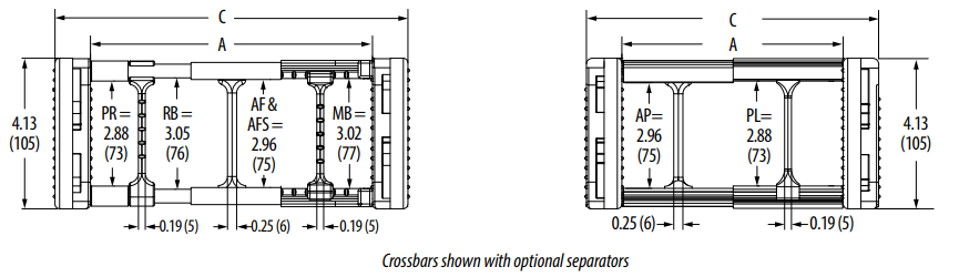
Cross Bar Styles: – MB = Snap-In Molded Plastic Flat Bar (fixed width)
– PR = Poly Roller (over bolted aluminum round bar)
– RB = Aluminum Round Bar
– AF = Aluminum Flat Bar
– AFS = Snap-Out Aluminum Flat Bar
– PL = Plastic Lid (enclosed design)
– AP = Aluminum Armor Plate (enclosed design)
Carrier Cross Sectional View
Model
Bar Style
A
(inner width)
C (outer width)
Weight (lb/ft)
TL
MB
3.94
5.87
2.80
TL
MB
4.66
6.59
2.85
TL
MB
5.73
7.67
2.90
TL
MB
7.88
9.82
2.95
TL
MB
9.68
11.62
3.00
TL
MB
11.84
13.77
3.05
TL
MB
13.63
15.57
3.10
TL
RB
Customer Specified
A + 1.94
3.42
TL
PR
Customer Specified
A + 1.94
3.72
TL
AF
Customer Specified
A + 2.01
5.21
TL
AFS
Customer Specified
A + 2.01
5.12
TL
PL
Customer Specified
A + 2.01
5.21
TL
AP
Customer Specified
A + 2.01
7.56
Specifications are listed as inches unless otherwise noted
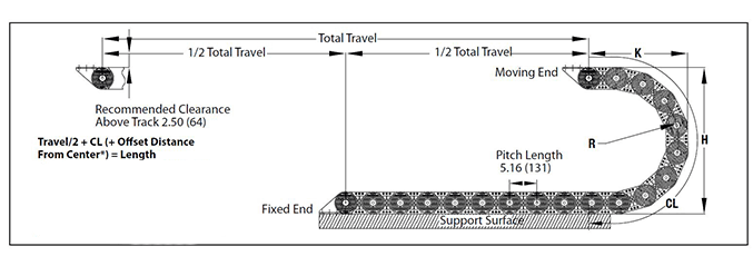
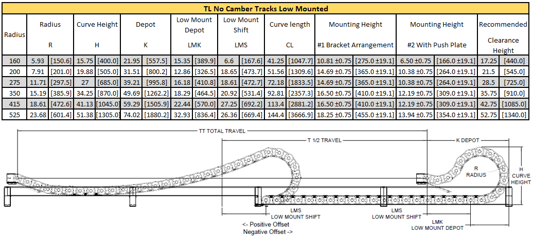
Carrier Side View
Travel/2 + CL (+ Offset Distance From Center*) = Length Dynatect recommends mounting the stationary end of the carrier at the center of travel, minimizing the required length.
In cases where center mounting is not possible, add the distance offset from center to the carrier length calculation.
Height
R (bend radius)
H (curve height)
K (depot)
CL (curve length)
160*
5.81
15.75
14.50
28.25
200
7.94
20.00
16.70
35.25
237
9.81
23.75
18.50
41.00
275
11.75
27.63
20.50
47.00
350
15.63
35.38
24.40
59.00
415
18.94
42.00
27.70
69.50
525
24.69
53.50
33.40
87.50
*The following options are not available with the 160 curve height: modular sliders, aluminum armor plates, plastic lids.
Specifications are listed as inches unless otherwise noted
Design Specs - Metric
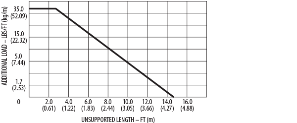
TL Series – Weight Load
How To Create A Part Number:
Model – Bar Style – Bar Width – Height – Separators – Length – Bracket (fixed) – Bracket (moving)
Example: TL-MB-5.73-160-0-72.23-#1IN-#1IN
⇒ Length is specified in inches, to two decimals. It is the distance between flanges ⇒ (see formula on carrier side view diagram)
⇒ Specify bracket type and arrangement # for each end
Cross Bar Styles: – MB = Snap-Out Plastic Flat Bar (fixed width)
– MB = Snap-In Molded Plastic Flat Bar (fixed width)
– PR = Poly Roller (over bolted aluminum round bar)
– RB = Aluminum Round Bar
– AF = Aluminum Flat Bar
– AFS = Snap-Out Aluminum Flat Bar
– PL = Plastic Lid (enclosed design)
– AP = Aluminum Armor Plate (enclosed design)
Carrier Cross Sectional View
Model
Bar Style
A
(inner width)
C (outer width)
Weight (kg/m)
TL
MB
100
149
4.17
TL
MB
118
168
4.24
TL
MB
146
195
4.32
TL
MB
200
249
4.39
TL
MB
246
295
4.46
TL
MB
300
350
4.54
TL
MB
346
395
4.61
TL
RB
Customer Specified
A + 49
5.09
TL
PR
Customer Specified
A + 49
5.54
TL
AF
Customer Specified
A + 51
7.76
TL
AFS
Customer Specified
A + 51
7.62
TL
PL
Customer Specified
A + 51
7.75
TL
AP
Customer Specified
A + 51
11.25
Specifications are listed as millimeters unless otherwise noted
Carrier Side View
Travel/2 + CL (+ Offset Distance From Center*) = Length Dynatect recommends mounting the stationary end of the carrier at the center of travel, minimizing the required length.
In cases where center mounting is not possible, add the distance offset from center to the carrier length calculation.
*The following options are not available with the 160 curve height: modular sliders, aluminum armor plates, plastic lids.
Height
R (bend radius)
H (curve height)
K (depot)
CL (curve length)
160*
148
400
368
718
200
202
508
424
895
237
249
603
470
1041
275
298
702
521
1194
350
397
899
620
1499
415
481
1067
704
1765
525
627
1359
848
2223
Specifications are listed as millimeters unless otherwise noted
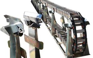
Mounting Brackets
Bracket Arrangements
Specify bracket arrangement (1, 2, 3, or 4) and mounting holes inward or outward
Standard Mounting Bracket Diagram & Dimensions
A (customer specified) = Cavity Width (bar/inside width)
Standard bracket layout shown above. Universal brackets are available:
TS Hybrid Carrier Long Travel System (Eliminates Guide Trough!)
The Hybrid carrier solution offers the lowest total cost of ownership (TCO) than any other long travel carrier solution, requires less space and averages 50% less installation time than standard long travel systems with guide troughs. The patented design consists of a modular plastic carrier with a metallic insert, delivering a truly revolutionary solution for long travel cable and hose management. Learn More & View Specs
ARS Long Travel System (Eliminates Guide Trough!)
Dynatect’s ARS Long Travel Support System adds articulating rollers that are positioned to support a standard plastic carrier and provide travels up to 300 feet without a guide trough. Learn More & View Specs